Steel Module Connection Planning: Responsibility, Load Path and Interface Coordination
A technical review of connection responsibility allocation, load-path concepts and interface coordination for steel modular construction — distinguishing fabrication, transport, lifting and in-service design situations.
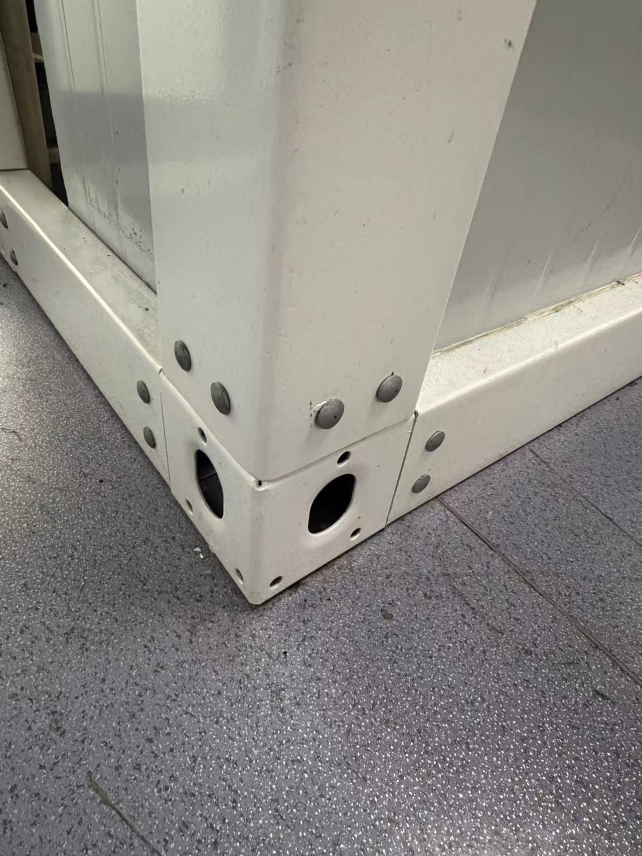
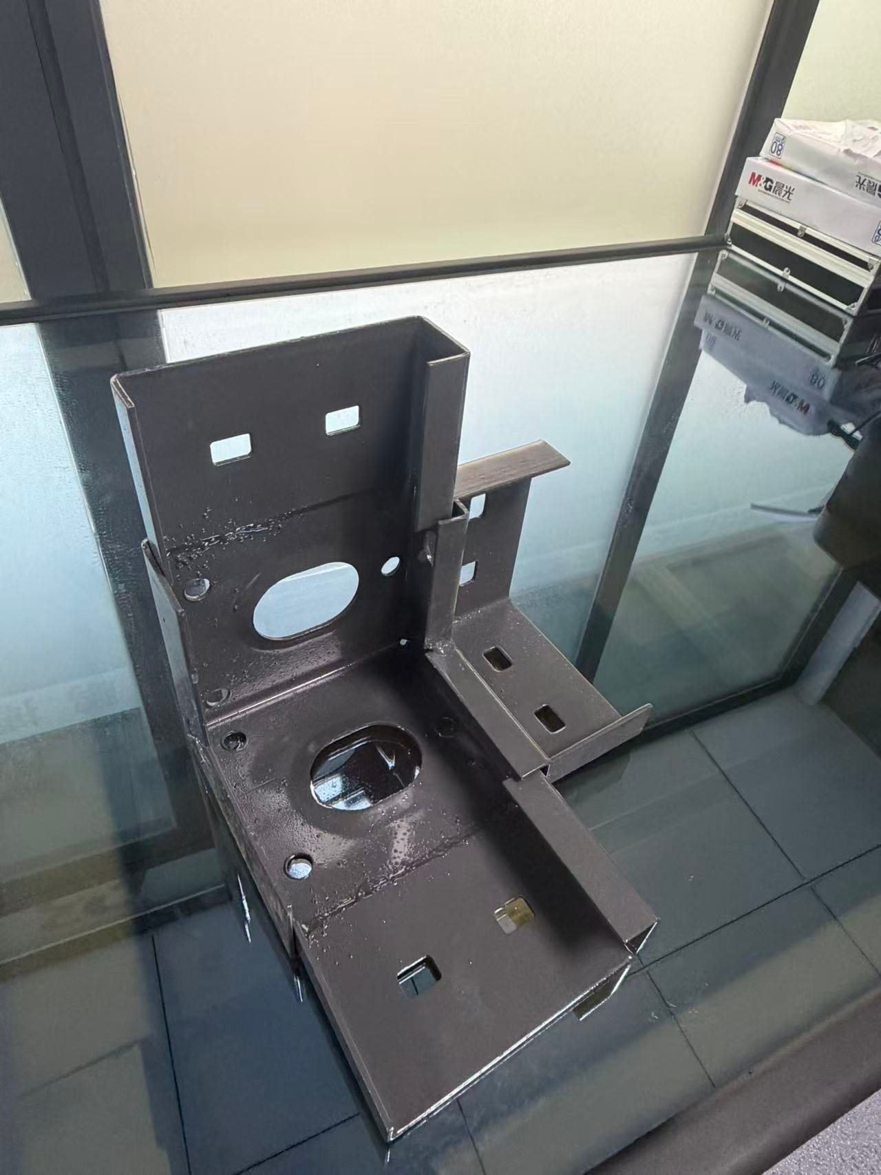
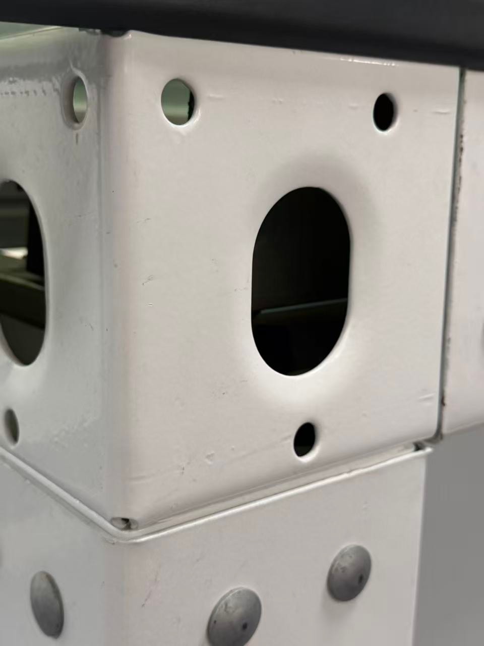
Methodology note: This article is an editorial technical review drawing on publicly available research and original analytical frameworks. It is not a peer-reviewed academic paper and does not constitute structural engineering advice. The photographs below show company-supplied factory photographs of corner connection components; they illustrate component form only and do not indicate steel grade, tested load capacity, certification status, or compliance with any specific standard. All structural and connection design decisions require a qualified structural engineer with knowledge of the specific project.
Abstract
Steel module connections in volumetric modular construction serve multiple functions across the project lifecycle: they transfer loads during fabrication handling, transport, lifting and in-service use, and they provide the structural interface between modules and between the modular stack and the building structure. The allocation of design responsibility for these connections — between the module supplier, the structural engineer and the main contractor — is a frequent source of coordination gaps. This review presents a responsibility and load-path framework for steel module connection planning, drawing on published research into intermodular connection design and original analysis of the interface conditions that arise in low-rise hotel projects.
Keywords: steel module connections, intermodular connections, load path, design responsibility, structural interface, modular construction
1. Scope and Approach
This review addresses steel module connections in the context of low-rise volumetric modular hotel construction. The analysis covers four design situations: fabrication and factory handling, transport, lifting and placement, and in-service loading. For each situation, the review identifies the primary load-path considerations, the typical responsibility allocation, and the interface coordination requirements.
The review draws on the abstract of a published review of connection design in modular steel construction [1], which confirms that connection behaviour depends on type and rigidity and that effective force transfer is a key design consideration. No numerical capacity data is derived from or attributed to this source. The responsibility framework and interface analysis are original to this review.
2. Design Situation 1: Fabrication and Factory Handling
2.1 Load-Path Considerations
During fabrication, modules are handled by overhead crane or forklift within the factory. The connection points used for factory handling may or may not be the same as those used for transport or site lifting. The load path during factory handling is typically through the module's own structural frame, with lifting points at the corners or designated pick points.
2.2 Responsibility Allocation
Factory handling is typically the responsibility of the module supplier. The supplier's structural engineer should confirm that the module frame and lifting points are adequate for the handling loads anticipated in the factory. This responsibility should be explicitly allocated in the supply contract.
2.3 Interface Coordination
The interface coordination requirement at this stage is confirmation that the factory handling method is consistent with the module's structural design. Changes to the handling method after structural design is complete may require re-analysis.
3. Design Situation 2: Transport
3.1 Load-Path Considerations
During transport, modules are subject to dynamic loads from road vibration, acceleration and braking. The load path is through the module frame to the transport vehicle's restraint points. The restraint method — chains, straps, twist locks — must be compatible with the module's structural connection points.
3.2 Responsibility Allocation
Transport restraint is typically the responsibility of the transport contractor, but the module supplier must confirm that the restraint method is compatible with the module's structural connection points. This interface responsibility should be explicitly allocated and documented.
3.3 Interface Coordination
The interface coordination requirement is a transport restraint plan that identifies the restraint points on the module and confirms their structural adequacy for the anticipated transport loads. This plan should be agreed between the module supplier and the transport contractor before transport begins.
4. Design Situation 3: Lifting and Placement
4.1 Load-Path Considerations
During lifting, the module is suspended from the crane hook through a lifting frame or spreader beam. The load path is through the lifting attachment points to the module frame. The lifting attachment points must be designed for the full module weight plus dynamic factors, and the lifting geometry must not impose unacceptable bending moments on the module frame.
4.2 Responsibility Allocation
Lifting design is a specialist activity. The lifting attachment points on the module are typically designed by the module supplier's structural engineer. The lifting frame or spreader beam is typically designed by the lifting contractor or a specialist lifting engineer. The interface between these two design responsibilities — the connection between the lifting frame and the module — must be explicitly allocated and coordinated.
4.3 Interface Coordination
The interface coordination requirement is a lifting plan that identifies the lifting attachment points, the lifting frame geometry, the crane capacity and the lift sequence. This plan must be agreed between the module supplier, the lifting contractor and the structural engineer before lifting begins. No lifting calculations are provided in this review; all lifting design must be carried out by a competent lifting engineer.
5. Design Situation 4: In-Service Loading
5.1 Load-Path Considerations
In service, modules must transfer vertical loads (self-weight, imposed loads) and horizontal loads (wind, seismic where applicable) through the intermodular connections to the building structure. The Australian Steel Institute notes that stacked modules may work with supplementary framing depending on the project [2]. The load path through the intermodular connections depends on the connection type and rigidity, as confirmed by published research [1].
5.2 Responsibility Allocation
In-service structural design is typically the responsibility of the project's structural engineer, who must confirm that the intermodular connections and the module-to-structure connections are adequate for the in-service loads. The module supplier's structural engineer is responsible for the module's own structural frame. The interface between these two design responsibilities — the intermodular connection — must be explicitly allocated.
5.3 Interface Coordination
The interface coordination requirement is a structural interface drawing that shows the connection between modules and between the modular stack and the building structure, with the design responsibility for each element clearly identified. This drawing should be agreed between the project structural engineer and the module supplier before fabrication begins.
6. Connection Responsibility Matrix
| Design Situation | Primary Load Path | Typical Responsibility | Interface Coordination Requirement |
|---|---|---|---|
| Fabrication / factory handling | Module frame to lifting points | Module supplier's structural engineer | Handling method confirmed against structural design |
| Transport | Module frame to transport restraint points | Transport contractor (restraint); module supplier (connection points) | Transport restraint plan agreed before transport |
| Lifting and placement | Lifting attachment points to module frame | Module supplier (attachment points); lifting contractor (lifting frame) | Lifting plan agreed; interface between lifting frame and module allocated |
| In-service loading | Intermodular connections to building structure | Project structural engineer (overall); module supplier (module frame) | Structural interface drawing issued and agreed before fabrication |
7. Limitations and Project-Specific Verification
This review does not provide structural calculations, connection capacity data or engineering prescriptions. All structural design decisions must be made by a qualified structural engineer with knowledge of the specific project, the specific module system and the applicable structural codes. The responsibility framework presented here is a coordination tool, not a substitute for engineering design.
Published research [1] confirms that connection behaviour in modular steel construction depends on connection type and rigidity. The specific behaviour of any connection in a specific project must be determined by the project's structural engineer, not inferred from general research findings.
Conclusion
Steel module connection planning requires explicit allocation of design responsibility across four distinct design situations: fabrication handling, transport, lifting and in-service loading. A potential coordination gap is the interface between the module supplier's structural design and the project structural engineer's design — particularly at the intermodular connection and the module-to-structure connection. Resolving this interface responsibility before fabrication begins is the single most important step in steel module connection coordination.
For information about steel modular room products and the structural documentation available, see our products page or contact us. Related reading: MEP Interface Coordination and Transport and Installation Planning.
References
- Gohar Nadeem, Nor Azizi Safiee, Nabilah Abu Bakar, Izian Abd Karim, Noor Azline Mohd Nasir (2021), Connection design in modular steel construction: A review, Structures 33, 3239–3256. sciencedirect.com — abstract verified; reviews intermodular connection techniques, geometries, behaviour and analysis; connection behaviour depends on type and rigidity; effective force transfer is a key consideration. No numerical capacity data is derived from this source.
- Australian Steel Institute, Modular Construction. steel.org.au — overview: stacked modules may work with supplementary framing depending on the project.
Topics
Explore our modular room products
Ready to discuss your project?
Our team is available to answer technical questions and provide indicative pricing for your modular construction project.
Contact Us