MEP Interface Coordination in Modular Construction: Factory, Site and Handoff
A technical review of the factory-to-site MEP connection responsibility matrix, tolerance management, access requirements and testing handoff for modular hotel projects.
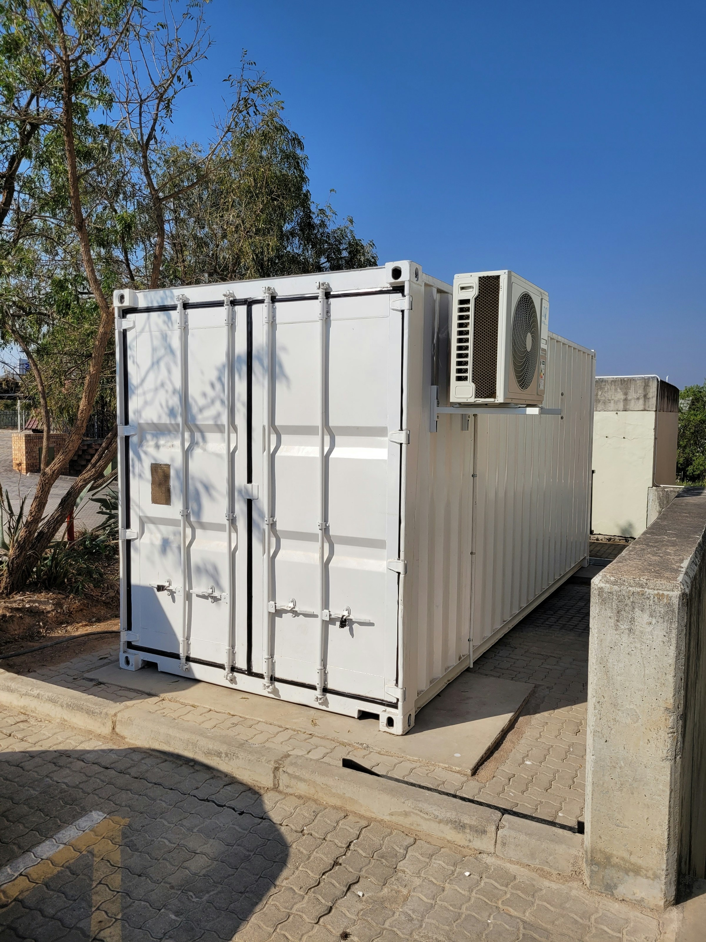
Methodology note: This article is an editorial technical review drawing on original analytical frameworks. It is not a peer-reviewed building services engineering paper and does not provide installation instructions. The photograph below shows a white container unit with external air-conditioning equipment as an illustrative reference for services coordination concepts; it is not a recommended installation detail or a Pengboxingchen product. Project-specific MEP design and installation require qualified building services engineers.
Abstract
MEP (mechanical, electrical and plumbing) coordination in modular hotel construction involves a fundamental split in responsibility: services within the module are designed and installed by the module supplier in the factory, while services outside the module — risers, mains, connections to the building plant — are designed and installed by the site contractor. The interface between these two scopes is a frequent source of coordination gaps, tolerance conflicts and commissioning delays. This review presents a responsibility matrix and coordination framework for managing the factory-to-site MEP interface in modular hotel projects.
Keywords: MEP coordination, modular construction, factory-site interface, building services, tolerance management, commissioning handoff
1. Scope and Approach
This review addresses the MEP interface between factory-installed services within modular hotel room units and site-installed services outside the modules. The analysis covers four service types: HVAC, electrical, plumbing and drainage. For each service type, the review identifies the typical factory/site responsibility split, the tolerance and access requirements at the interface, and the testing and commissioning handoff requirements.
2. The Factory-Site Interface Problem
The fundamental challenge of MEP coordination in modular construction is that two separate design and installation processes — factory and site — must produce services that connect precisely at the module boundary. The factory installation is complete before the site installation begins, which means that the interface connection points must be designed and built to a tolerance that the site installation can reliably achieve.
When this coordination fails, the consequences are typically: connection points that do not align, requiring field modifications that may compromise the integrity of the factory installation; services that cannot be tested independently because the connection is not yet made; and commissioning delays while interface problems are resolved.
3. HVAC Interface
3.1 Responsibility Split
Factory scope typically includes: fan coil units or split system indoor units; ductwork within the module; condensate drainage within the module; and refrigerant pipework within the module to a connection point at the module boundary. Site scope typically includes: refrigerant pipework from the module boundary to the outdoor unit or central plant; condensate drainage from the module boundary to the building drainage system; and fresh air supply and exhaust connections at the module boundary.
3.2 Tolerance and Access Requirements
The refrigerant pipework connection at the module boundary must be accessible for brazing or mechanical connection, pressure testing and leak detection. The connection point location must be coordinated between the factory design and the site design to within the tolerance achievable by both. Typical tolerance requirements for refrigerant pipework connections are tighter than for drainage connections; the specific tolerance must be agreed between the factory and site designers.
3.3 Testing and Commissioning Handoff
Factory testing of HVAC systems within the module should be completed before dispatch, with test records provided to the site contractor. Site testing of the complete system — including the site-installed connections — is a separate activity that cannot be completed until all connections are made. The commissioning plan should identify the sequence of testing activities and the handoff point between factory and site responsibility.
4. Electrical Interface
4.1 Responsibility Split
Factory scope typically includes: all wiring within the module; distribution board within the module; lighting and power outlets; and a connection point at the module boundary for the incoming supply. Site scope typically includes: the incoming supply cable from the building distribution board to the module connection point; and earthing connections at the module boundary.
4.2 Tolerance and Access Requirements
The electrical connection point at the module boundary must be accessible for connection, testing and isolation. The connection method — plug-and-socket, terminal block or direct cable connection — must be agreed between the factory and site designers and must be compatible with the site installation method.
4.3 Testing and Commissioning Handoff
Factory testing of the electrical installation within the module should include insulation resistance testing and continuity testing, with records provided to the site contractor. Site testing of the complete installation — including the incoming supply and earthing — is a separate activity. The electrical inspector should be aware of the factory-site split and should confirm that the combined installation meets the requirements of the applicable electrical standard.
5. Plumbing Interface
5.1 Responsibility Split
Factory scope typically includes: all hot and cold water pipework within the module; sanitary fittings; and connection points at the module boundary for hot and cold water supply. Site scope typically includes: hot and cold water supply from the building risers to the module connection points; and isolation valves at the module connection points.
5.2 Tolerance and Access Requirements
The water supply connection points at the module boundary must be accessible for connection, pressure testing and isolation. The connection method and pipe size must be agreed between the factory and site designers. Isolation valves at the module connection points are essential for maintenance and remediation; their location must be accessible without removing the module.
6. Drainage Interface
6.1 Responsibility Split
Factory scope typically includes: all waste and soil pipework within the module; and a connection point at the module boundary for the drainage stack. Site scope typically includes: the drainage stack from the module connection point to the building drainage system; and access provisions for the stack.
6.2 Tolerance and Access Requirements
The drainage connection at the module boundary must achieve the correct gradient for the site drainage system. The gradient requirement must be communicated to the factory designer before the module floor level is fixed. Access to the drainage connection for inspection and clearance must be provided without requiring module removal.
7. MEP Responsibility Matrix
| Service | Factory Scope | Site Scope | Interface Requirement | Testing Handoff |
|---|---|---|---|---|
| HVAC | FCU/indoor unit; ductwork; condensate drain; refrigerant to boundary | Refrigerant from boundary to outdoor unit; fresh air/exhaust connections | Connection point location and tolerance agreed; access confirmed | Factory: system test before dispatch. Site: complete system commissioning after connection |
| Electrical | All wiring; distribution board; lighting/power; supply connection point | Incoming supply cable; earthing | Connection method agreed; access confirmed; isolation provision | Factory: IR and continuity test. Site: complete installation test per applicable standard |
| Plumbing | Hot/cold pipework; sanitary fittings; supply connection points | Supply from risers to connection points; isolation valves | Connection method and pipe size agreed; isolation valve location accessible | Factory: pressure test before dispatch. Site: complete system pressure test after connection |
| Drainage | Waste/soil pipework; drainage connection point | Stack from connection point to building drainage | Gradient requirement communicated to factory; access to connection confirmed | Factory: flow test before dispatch. Site: complete drainage test after connection |
8. Limitations and Project-Specific Verification
The responsibility split and interface requirements identified in this review are illustrative. The specific requirements for any project will depend on the module specification, the building services design, the applicable standards and the procurement route. The framework should be adapted by the project team — including the building services engineer, the module supplier and the site contractor — to reflect the specific conditions of each project. This review does not provide installation instructions; all MEP installation must be carried out by qualified and licensed contractors.
Conclusion
MEP interface coordination in modular hotel construction requires explicit allocation of responsibility at the factory-site boundary for each service type, agreement on connection methods and tolerances before factory production begins, and a structured testing and commissioning handoff plan. A potential coordination failure is the assumption that the interface will be resolved during installation; in modular construction, interface problems discovered during installation are significantly more costly to resolve than those identified during design.
References and Further Reading
The following sources provide relevant background to this article. This editorial review has not undertaken a systematic study of industry data; statements about coordination considerations reflect the analytical framework presented here.
- Further reading: UK Government, Volumetric Modular Construction Research, published 26 November 2024 (research finalised July 2022, England scope). gov.uk — provides context on pre-project planning and lifecycle interface ownership in modular construction outcomes.
- Further reading: AIA–NIBS, Modular and Off-Site Construction Guide (2019). nibs.org — industry guide covering off-site construction coordination principles.
For information about MEP coordination documentation available for Pengboxingchen modular room products, see our products page or contact us. Related reading: Bathroom Pod Design Coordination and Steel Module Connection Planning.
Topics
Explore our modular room products
Ready to discuss your project?
Our team is available to answer technical questions and provide indicative pricing for your modular construction project.
Contact Us